
This is an article in a story format, about the design of the space segment software for the FUNcube missions, from FUNcube-1 (AO-73) in 2013 to the present day with JY1SAT (JO-97, launched 3 Dec 2018 - finally!).
[edit to add] JY1SAT signals received in Australia, we have another worker! http://data.amsat-uk.org/ui/jy1sat-fm
First, it takes a number of widely skilled, experienced and professional people to build spacecraft software, I take very little credit for the working satellites :)
The Dev Team
The FUNcube team, in particular for the space segment software:
- Duncan Hills (M6UCK) - the main man: seasoned hacker, relentless worker, practicality expert, LED enthusiast..
- Wouter Weggelaar (PA3WEG) - the ringer: by day a mild mannered space technology company employee, by night: AMSAT-NL guy!
- Gerard Aalbers - the professional: eagle eyed reviewer, standards enforcer, bug hunter, puzzle solver and unflappable dude.
- Howard Long (G6LVB) - the SDR wizard: algorithm creator, Microchip PIC abuser, RF engineer, fancy 'scope owner.
- Jason Flynn (G7OCD) - the hardware guru: PCB layout wizard, Freescale blagger, KISS guy, watchdog layering fan, Verilog god.
- Phil Ashby (M6IPX) - me, the troublemaker: daft ideas, prototypes, fail fast breakages, repository guardian, loudmouth.
TL;DR
When designing, creating & testing software for a satellite, apply a few rules to keep your sanity:
- Keep It Simple Stupid (KISS),
- Use your language wisely, we tried to apply the NASA JPL coding standard C
- Trace everything like a logic analyser (esp. from space),
- Build in remote debug features (you are gonna need 'em),
- Create one tested feature at a time (agile behaviour driven design),
- Use idempotent, absolute commands, no toggles.
- If you think it's done test it again (too many external variables),
- Use the LEDs Luke, because flashing lights are fun!
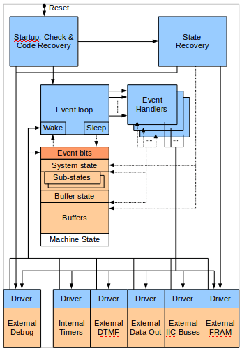
The Obligatory Diagram
This is almost how it works..
A Little Background
More is available at The FUNcube Website.
AMSAT-UK & AMSAT-NL started development of a new satellite in 2009, our colleague Jason, a member of AMSAT-UK, volunteered to design and develop the Command, Control & Telemetry (CCT) board, as he had previous experience with other satellite design work. The CCT provides the 'brains' that allow operators on the ground to control the satellite, and collects lots of telemetry from on board sensors for educational purposes. The CCT had to meet a number of objectives:
- The functional specification :)
- Low power (under 100mW), we wanted all the juice for the transmitter.
- Fail safe, part of the Cubesat regulations to protect other systems from interference, we can't 'go rogue'.
- Persistant storage, to meet the educational brief we needed to have historical data available at all times.
- Resilience, specifically in the face of failing peripheral devices & the battery wearing out.
- Low maintenance, needs to keep doing what it was last told to without lots of commanding from the ground.
With hardware design underway, Jason asked Duncan & I to assist with the software, as AMSAT-UK / AMSAT-NL were unsure of the available development time (launch schedules are tricky things for Cubesats) and wanted to ensure that the CCT was adequately tested before launch.
So how does one respond when asked 'would you like to write code to go into space?' - hell yeah!
So What Are We Programming?
The CCT hardware consists of a two layer design (did I mention Jason likes layers?):
- A programmable logic chip (CPLD) that has just enough logic to: decode a simple command protocol (sorry, we can't discuss details!) enabling other to parts to be turned on/off; provide a digital to analogue convertor (DAC) for modulating the downlink radio. This is a Xylink CoolRunner-II.
- A micro-controller (MCU) to: collect telemetry, encode it into an audio signal for the DAC / modulator; decode and implement more complex commands that provide the majority of the functional specification. This is a Freescale (now NXP) HCS08 series 8-bit device, with 128k of banked ROM, 6k of RAM and a 16-bit address bus. It has a maximum clock speed of 40MHz.
These parts were chosen for appropriate I/O ability (such as I2C, SPI), low power (eg: no external oscillators), previous design experience with them and available tooling (ie: Code Warrior Free Edition).
Where Do You Start?
Well, Jason concentrated on the hardware & CPLD, his area of expertise and a critical part of the fail safe design that needed to be proven early on. Much as I'd love to talk you though the Verilog, it's not where my skills are, let's assume that all worked just fine, although the DAC was challenging :)
Duncan & I took on the MCU:
- Working with Jason to define an interface protocol with the CPLD, including a watchdog mechanism (did I mention Jason likes watchdogs?), received command transfers and DAC sample output.
- Working with Howard to embed the data encoding and forward error correction (FEC) software: we use a variant of the scheme created by Phil Karn (KA9Q), James Millar (G3RUH) et al. for an earlier AMSAT spacecraft, Oscar-40, commonly known as AO-40 FEC
- Working with Gerard to ensure compliance with Cubesat & coding standards, safety & reliability in operation.
- Working with Wouter to ensure correct radio modulation and reception (Wouter is also in the RF design team).
- Communication with a number of inter-intergrated circuit (I2C) devices for telemetry data and other purposes.
- Managing a persistent ferro-electric random access memory device (FRAM) over serial peripheral interface (SPI).
- Sampling a number of local analogue input pins via the built-in analogue to digital convertor (ADC) for yet more telemetry.
- Controlling the deployment of the spacecraft: the remove before flight switch, the launch delay and the aerials.
Did I mention that our satellite power supply has a watchdog that we need to reset over I2C or it turns everything off and on again? Can't have too many watchdogs it seems...
Can We Clock It?
So we have a tiny MCU by modern expectations, it's not much more than a fast 6805 or Z80, can it do all the things we need to? We can reduce the clock frequency (yes, underclocking!) to save power, how fast do we need to go?
We choose to work through the actions required, the timing requirements for inputs and outputs and the processing load (cycle counts), to find out:
- Actions are a regular affair: data collection schedules for each sensor (1/5/60 seconds), packing that data into frames and encoding them for transmission, something that a state machine & sequential code could handle just fine given a clock.
- Timing for inputs is non-critical: commands are asynchronous with response times in seconds, telemetry collection is on a schedule where repeatability matters more than absolute sample timing.
- Timing for outputs turns out to be more stringent, as we are generating audio samples at 9600Hz that have to be accurate to a few microseconds, and telemetry frames need to be sent continuously.
- Processing load (measured in CPU cycles - determined by prototyping and clock counting), is minimal during data collection, however there is significant work required to apply the FEC which mustn't disrupt other activities.
Once we have an idea of the processing load, we can choose a clock frequency that gives us good headroom while keeping the power levels down - we end up at 14MHz and an estimated power consumption of 50mW with twice the number of cycles than we expect to use.
Our MCU also has a specific power saving WAIT instruction that suspends the CPU clock until an interrupt wakes it up, so by designing out busy waits / polling we should save more power - can we clock it? Yes we can.
Will an OS Help?
An internet search for MCU operating systems will find libraries such as FreeRTOS, CMX-TINY or uC/OS-II. With the RAM we have these can typically squeeze in a task manager with preemption, message queues and timers.
Do we need these features? Do we want to be debugging 3rd party RTOS code?
Applying the KISS principle: we choose to avoid complex, non-deterministic things like memory managers, task pre-emption / scheduling, priority queues, etc. as we feel our challenges can be largely met by a state machine and some careful timing. In addition we still have to provide all the device drivers ourselves, so a 3rd party OS isn't really helping much. We choose to work with the bare MCU and the device libraries provided by the tooling (thanks Metroworks/Freescale/NXP!)
Event Loops & Buffers
The only way we can meet the real time audio output timing is under interrupt from a hardware timer. With this interrupt in place, we have a means to 'wake up' the MCU from the WAIT instruction and feed it timing events (in practice a 100 millisecond pulse) via a bit in shared variable. This leads to a design where the main loop is a single threaded event processor, dispatching timing or other input data events, delivered under interrupt to avoid busy waiting. While processing events we also reset the various watchdogs, which allows them to detect / correct any failure in the wake up mechanism.
See the diagram above :)
Our other challenges are continuous telemetry and fitting in enough cycles to apply FEC. These can be met by double buffering the telemetry data, thus we are sending a processed frame as audio output under interrupt while encoding the next. This adds a delay to the telmetry (one frame, 5 seconds) but allows us to spread out the FEC processing over a frame period, slotting in bursts of activity on a predictable schedule.
Double buffering consumes a big chunk of our RAM (each frame buffer is 650 bytes), and on numerous occasions we have to re-arrange variables or refactor the code to remove them so eveything fits back into 6k!
Persistance, Resilience & Low-mantenance
All the -ences (almost). Did I mention that we like watchdogs? Our MCU has an internal reset watchdog that we enable early on, and have to clear every 125msecs. This gives us confidence that should something go very wrong and we deadlock or spin while processing an event, we get restarted. We make use of this to detect bad devices while performing I/O, by storing a device ID just before collection, and on restarts, checking for a watchdog timeout (it usefully tells us it had to restart the MCU), then checking for a device ID, and if found, excluding that device from the next execution (ground commands can reset this state however to retry failed devices).
We also have little faith in RAM keeping it's value during power glitches (brown-outs), that are likely as the battery loses capacity over time, thus all important data structures have a cyclic redundancy check (CRC) in, which is checked during restarts. If that fails we can take appropriate action, either resetting to defaults or obtaining a backup from persistent FRAM. We CRC the FRAM contents too - there are cosmic rays in space that can mess up storage!
For that low-maintenance requirement, we have FRAM storage for all system configuration structures and restore these on restarts as above.
Debugging, Tracing and Avoiding Toggles
It's really easy to debug an embedded device when it's on the desk in front of you - attach the programming pod and hit F5 in your IDE. Because of this, our initial thoughts on using a serial port as a debug console were scrapped, not worth it when there are better tools to hand. However, once working with a built satellite that cannot have the pod attached, we find a stack of LEDs on spare I/O pins to be very useful, you can show critical state bits / important transitions (like starting the event loop) and see timing heartbeats.
Once out of pod or visible range (aka in space), we need a way to examine internal state / manipulate peripherals / trace execution, so we include a number debug commands that allow memory block dumps, I2C bus transactions and can hard reset the CCT.
Our favorite feature in this area is the execution trace - based on hardware logic analyser design, we write short messages (2-4 chars) into a trace buffer during execution, and include this buffer in regular telemetry output, always from the most recent message and going backwards in time. This allows us to see things like our startup logic flow at each reset or identify unusual data inputs, giving us opportunities to reproduce unusual conditions and debug on the local engineering model that's still within reach!
From remote debugging we learnt never to have 'toggle' commands, it's unsafe and difficult to determine if the command worked, you have to try to read back the old and new states to compare them... much better to always set a specific state and have a command acknowledgement scheme (we use a command counter). This makes commands idempotent, allowing blind commanding by resending the same one multiple times (aka, shouting at your satellite!), very useful if that command is 'deploy the aerials'...
FIN


